VALVES AND ACTUATORS
36
valves sizing
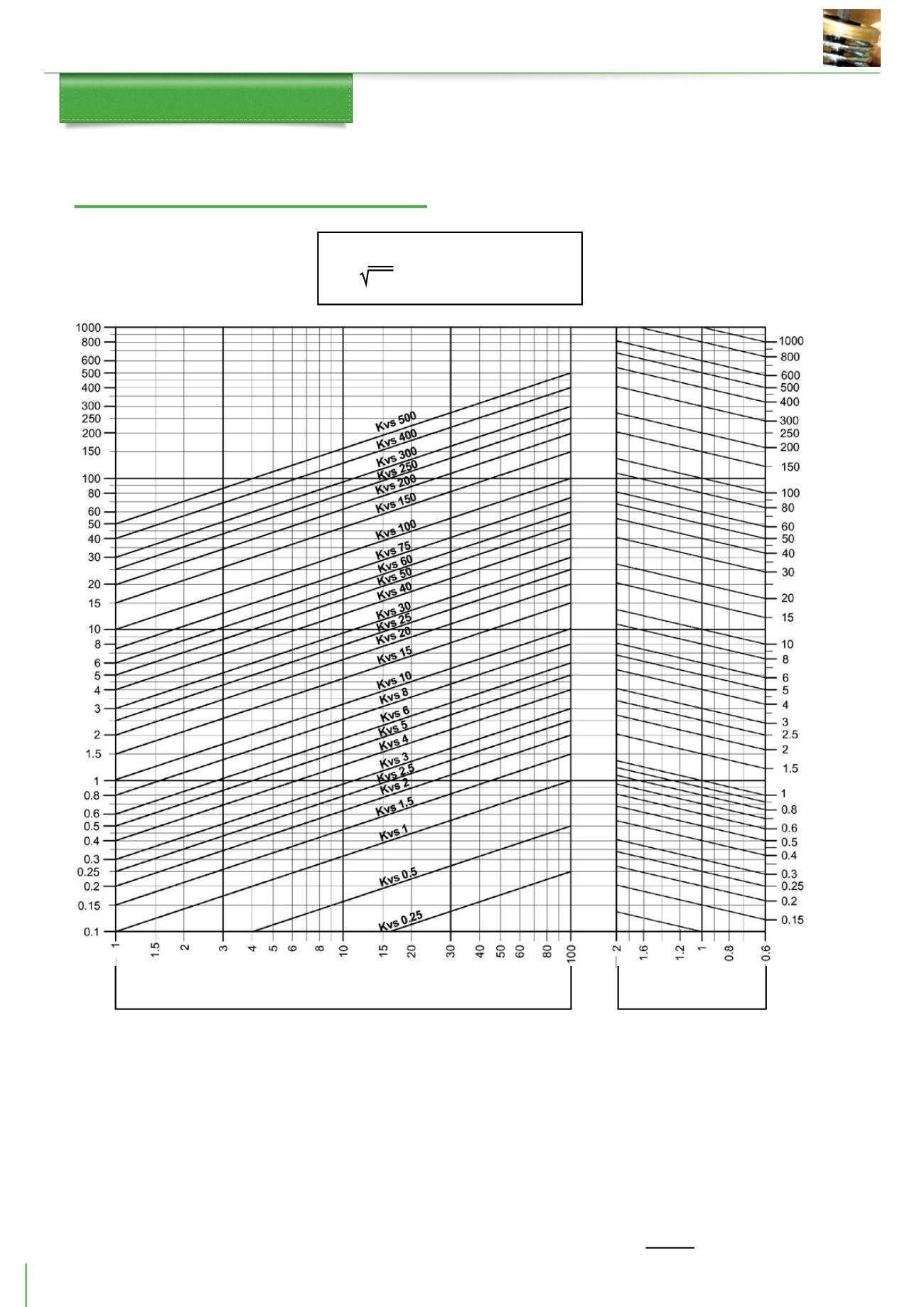
Valve Sizing Diagram for Fluids
Kvs = Q10
D
pv
Q = flow rate in m
3
/h
D
pv = pressure drop in kPa
Water flow rate in m
2
/h
Flow rate in m
2
/h
Pressure drop kPa
(100 kPa = 1 bar = ~ 10 m H
2
O)
Liquids with volume dif-
ferent from 1kg/dm
3
NOTA: the recommended valve pressure drop must be at least equal
to the load.
Example for fluids with relative density1 kg/dm
3
(water)
In order to size a control valve with:
FLOW RATE: 7.5 m
3
/h of water
PRESSURE DROP: 55 kPa
Use the diagram as follows:
- Identify the crossing point between the line starting from the flow
rate value (7.5 m
3
/h) and from the pressure drop value (55 kPa).
This point corresponds to the required flow coefficient,i.e.Kvs 10.There-
fore, the control valve must have Kvs 10.
Example for liquids having relative density different from 1 kg/dm
3
In order to size a control valve with:
FLOW RATE : 150 m
3
/h having (0.9 kg/dm
3
) relative density
PRESSURE DROP: 80kPa
Use the diagram as follows:
Identify the crossing point (right side of the diagram) between the line
starting from the relative density value (0.9 kg/dm
3
) and the inclined
line starting from the flow rate value (150 m
3
/h).
Identify the crossing point between the line starting from the crossing
point above and the other from the pressure drop value (80 kPa).
This point corresponds to the required flow coefficient. Therefore, the
control valve must have approximately kvs 160.
Example with diathermic oil.
It could be convenient to size the valve on diathermic oil using the wa-
ter diagram.To do this, it is necessary to apply the following conversion
formula, which takes into account the mass and the “average” specific
heat of diathermic oil:
Q = K calories in m
3
/h = water
D
t 500


